Servos
Servo 101
- Check servo directions – For example, apply some collective to verify cyclic servo movement. Reverse servos if necessary.
- Level the servo arms – Enable Servo Override and adjust Center until each arm is perpendicular to the main shaft.
- Set scaling – Use Scale neg and Scale pos to achieve correct servo angles. With Servo Override active, specify an angle of 30°. If the servo moves less, increase Scale pos; if it moves more, decrease it. Repeat for Scale neg.
- Adjust limits only for mechanical issues – Use Min or Max to prevent binding or extend travel if required. For range adjustment of roll, pitch, or collective, use the mixer instead.
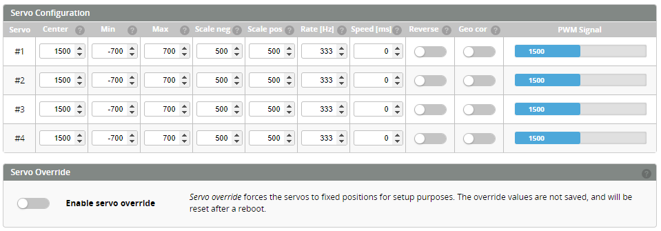
Servo Configuration parameters
Center
Use Center to level the servo arms. Ideally this is around 1500 µs for cyclic servos and 750 µs for tail servos, but some servo arms may require significant adjustment, and values like 1400 µs for center are not uncommon.
Min and Max
Min and Max define the hard limits to keep servos from binding or exceeding their mechanical range. If a servo is driven beyond what it can physically handle, it may buzz, damage components, or even burn out.
Scale Neg and Scale Pos
Scales the negative and positive direction of the servo to match the commanded angle.
Rate
This sets the servo PWM update frequency, as specified by the manufacturer. Most modern digital servos support 333 Hz, while most analog servos should be set to 50 Hz.
Use separate timers for different update rates. All known Rotorflight flight controllers dedicate a timer to the tail servo, allowing it to always run at its optimal frequency.
Speed
Sets the servo speed and can be used to equalize servo movement. Speed equalization helps eliminate the collective "bobbing" that can occur during rapid elevator changes.
Bobbing happens because the elevator servo often needs to move twice the distance of the aileron servos. If the elevator servo can’t keep up, the aileron servos reach their target before the elevator servo, causing the swashplate to shift slightly.
To tune this, increase the speed value (measured in ms/60°, as in the servo datasheet) until the bobbing disappears. If unsure, using the value from the servo datasheet is always safe.
Reverse
Toggle for forward or reverse servo direction.
Geo Cor
Geometry Correction: since servos are rotary, large servo angles produce smaller swashplate movement per degree of servo rotation. Geometry correction compensates for this, giving better control at high swashplate angles (e.g., during 3D flight).
To use this feature correctly, make sure the servo arm is set at 90° with the servo centered, and calibrate the servo scale.
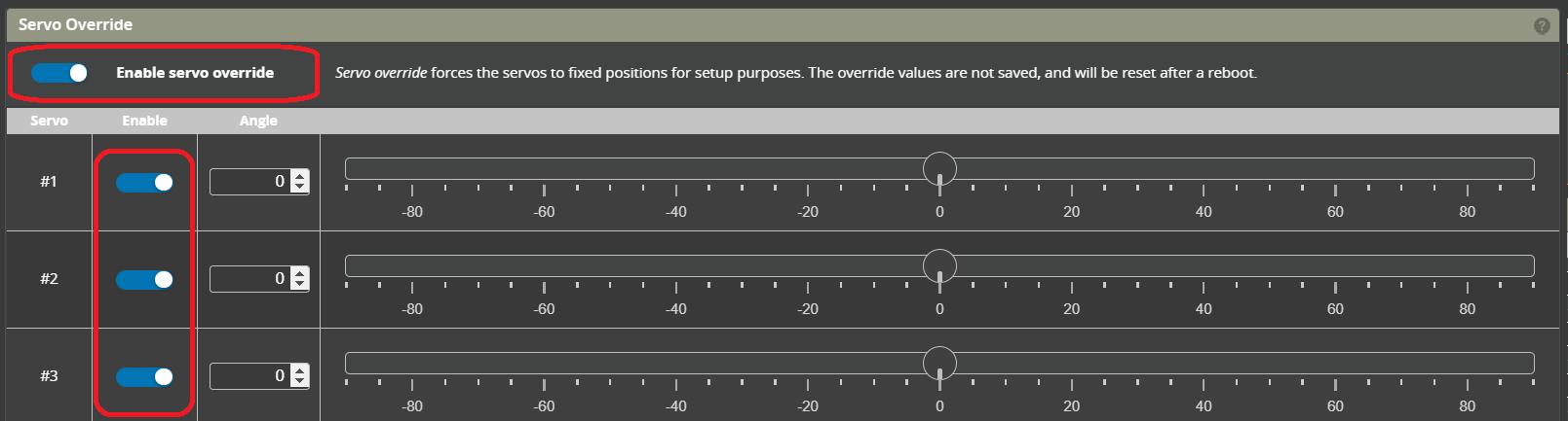
Servo Override
The toggle at the bottom of the page enables servo overrides, allowing each servo to be moved with a slider for calibrating its range and center. Each servo also has its own individual override control.
The servo override slider scale is in degrees
Servo Numbering
CCPM: Cyclic/Collective Pitch Mixing
CCPM is a control system where multiple servos work together to move a helicopter’s swashplate for both cyclic and collective pitch. It is the most common system used in model helicopters today.
For 120, 135 and 140 deg CCPM swashplates, looking from the tail towards the nose of the helicopter:
Servo 1 - Pitch (inline with the centerline of the helicopter)
Servo 2 - Left side
Servo 3 - Right side
Servo 4 - Rudder

Fixed pitch
90deg L
Servo 1 - Pitch (inline with the centerline of the helicopter)
Servo 2 - Side servo
Servo 3 - Rudder

90deg V
Servo 1 - Left side
Servo 2 - Right side
Servo 3 - Rudder

Direct
For helicopters that uses mechanical mixing, where the Pitch, Roll, and Collective movements are each controlled by a dedicated servo by means of a complex series of linkages and levers from the servos up to the swashplate.
Servo 1 - Pitch
Servo 2 - Roll
Servo 3 - Collective
Servo 4 - Rudder